Electronics Design
For this week's assignment, It was required to:
Individual
Redraw the echo hello-world board-3D scan an object
Add (at least) a button and LED (with a current-limiting resistor)
Check the design rules, make it, and test it
Group
Use the test equipment in your lab to observe the operation of a microcontroller circuit board
Eagle
EAGLE is a scriptable electronic design automation (EDA) application with schematic capture, printed circuit board (PCB) layout, auto-router and computer-aided manufacturing (CAM) features. EAGLE stands for Easily Applicable Graphical Layout Editor and is developed by CadSoft Computer GmbH. The company was acquired by Autodesk Inc. in 2016.
Eagle is the most preferable because a lot of open source projects are available in eagle .It is easy to use easily understandable and have a well back of active users.
Starting with eagle
First thing to do is install Eagle, after that, set it up. Once Eagle is installed, download the Fab library that provides you with all the components you need for this board.
To implement your board on Eagle, you need few steps:
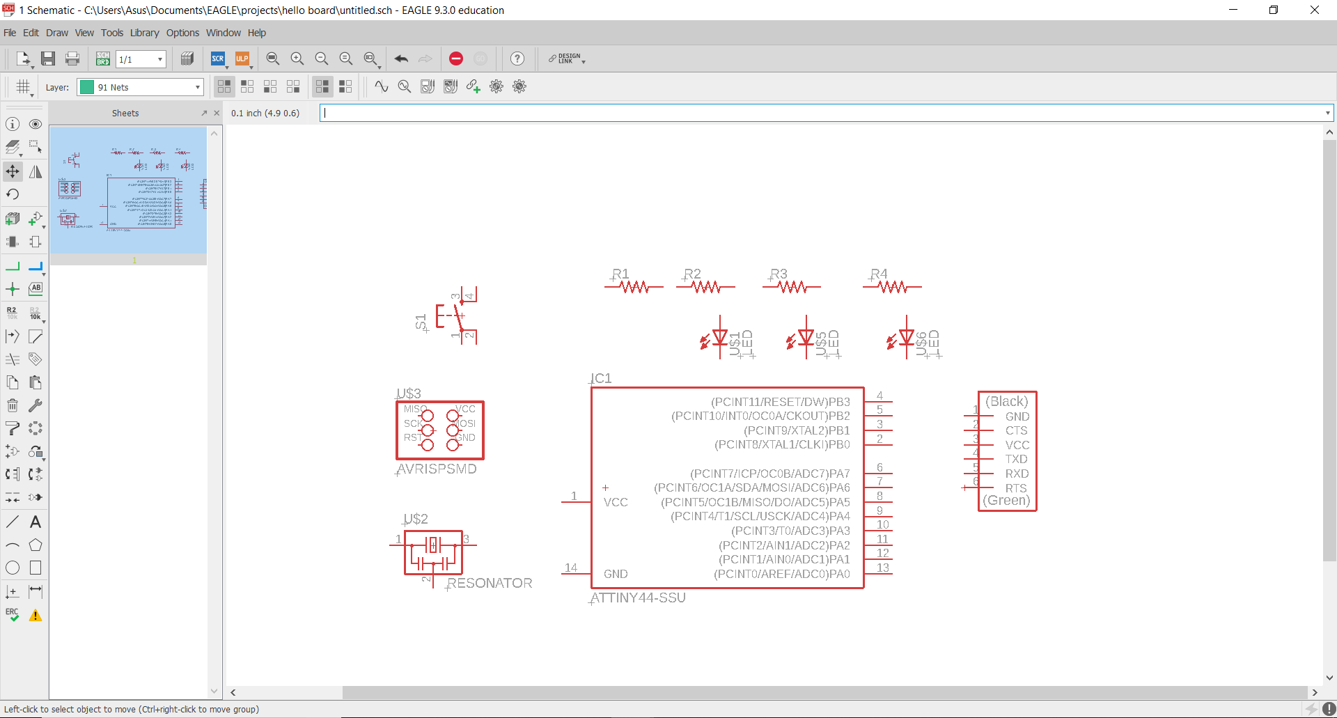
1. Sketch your board in Schematic view and connect the components.
2. Switch to board view and arrange your components.
3. Route your components.
4. Check your board by ERC (Electical Rules check) and DRC (Design Rules Check).
5. Prepare your board for machining as previouly done in Electronics Production week.
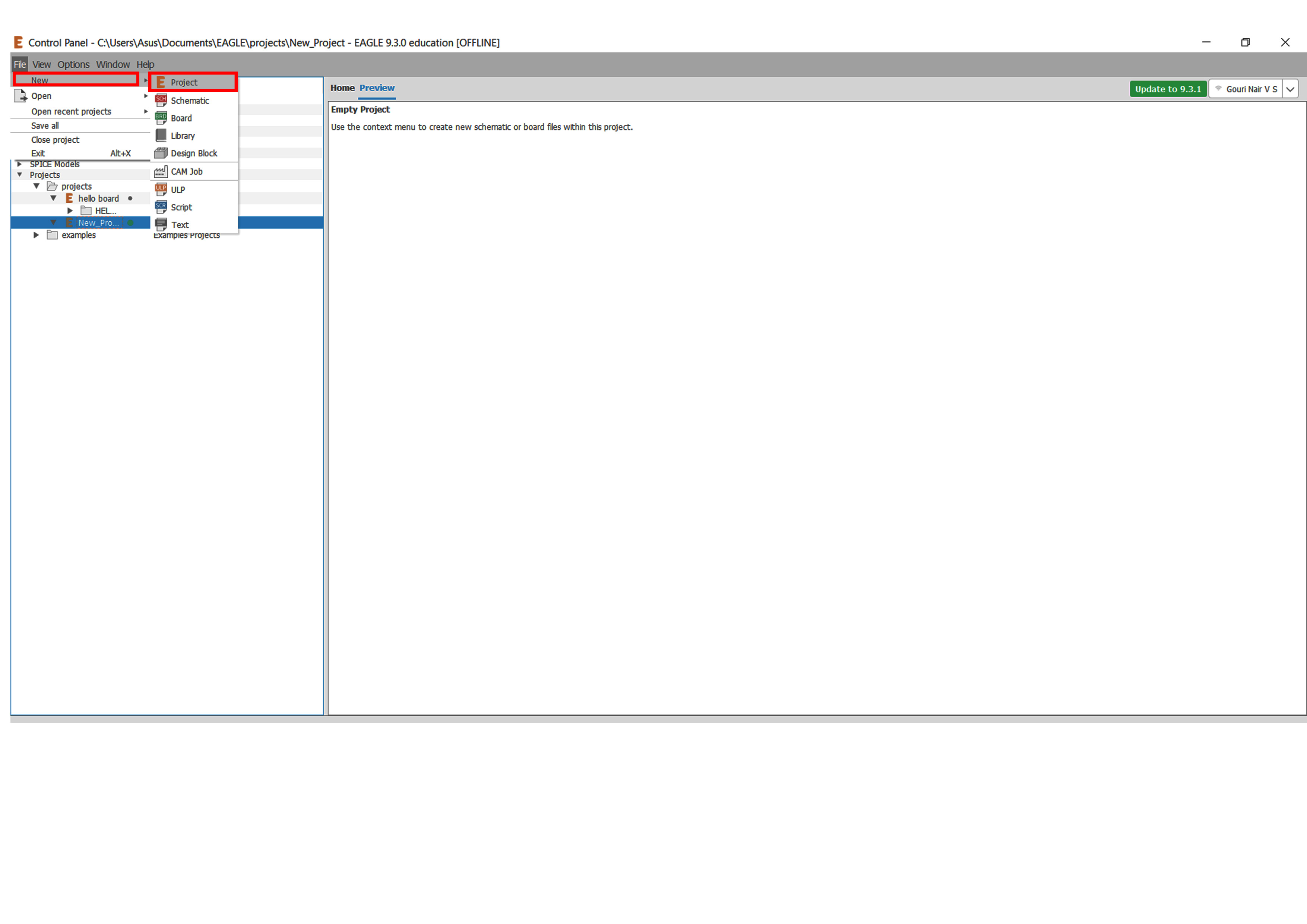
Fire up the eagle software and a new project can be created from the file menu
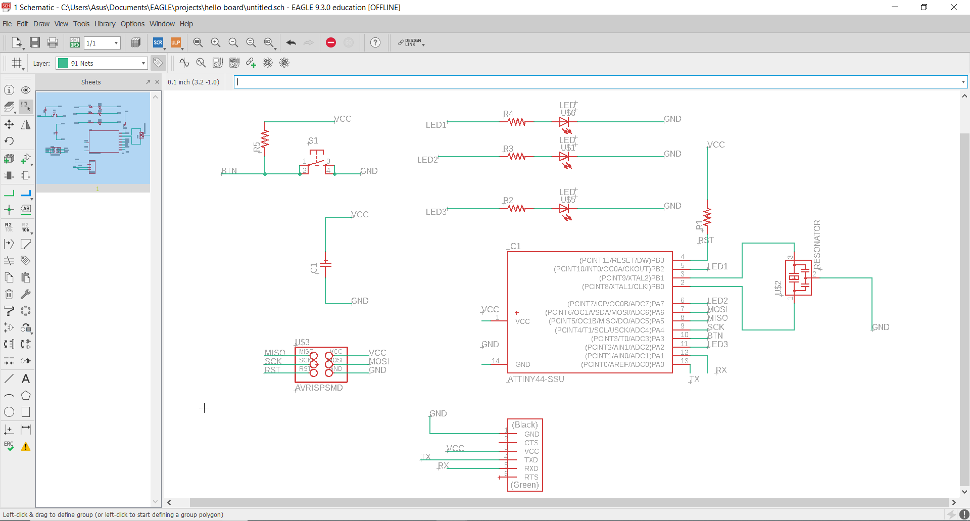
After adding the components, connect them using the "wire" option. Sometimes, connections get messy; so as optimization, name your connections you want to connect together using same names and you'll find eagle asking you if you want to connect themm; click "Yes". For that, use "Name" command. This is will make your schematic look a little bit neat, and it will be more organized. Finally, to avoid confusion, add "label" to connections.
Now we have to set the design rules for modella MDX200. For that I open "Design rules" under "Edit"
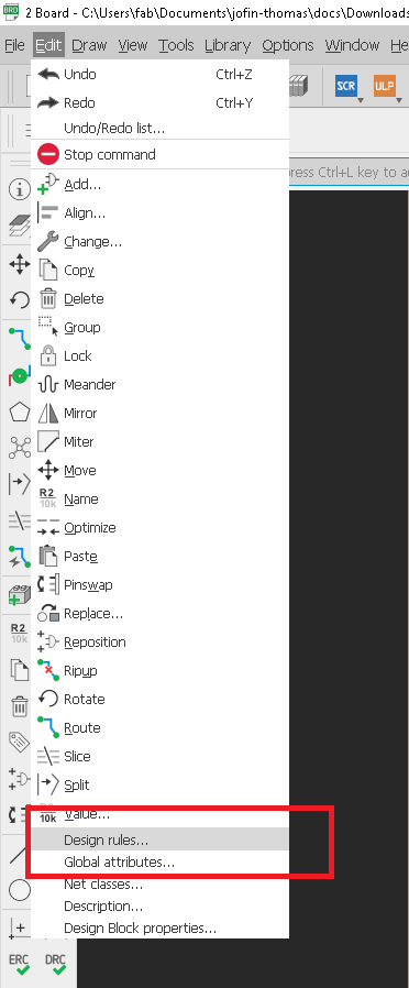
First open design rules
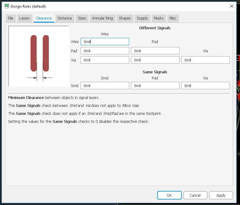
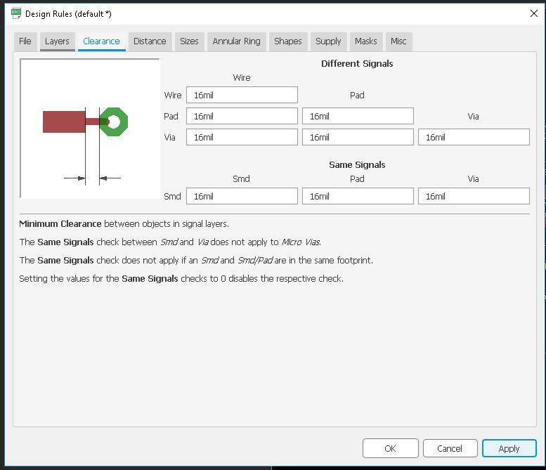
Then we need to set the Clearnce , we are using 1/64 bit for milling so here the trace will come around 16 mill.
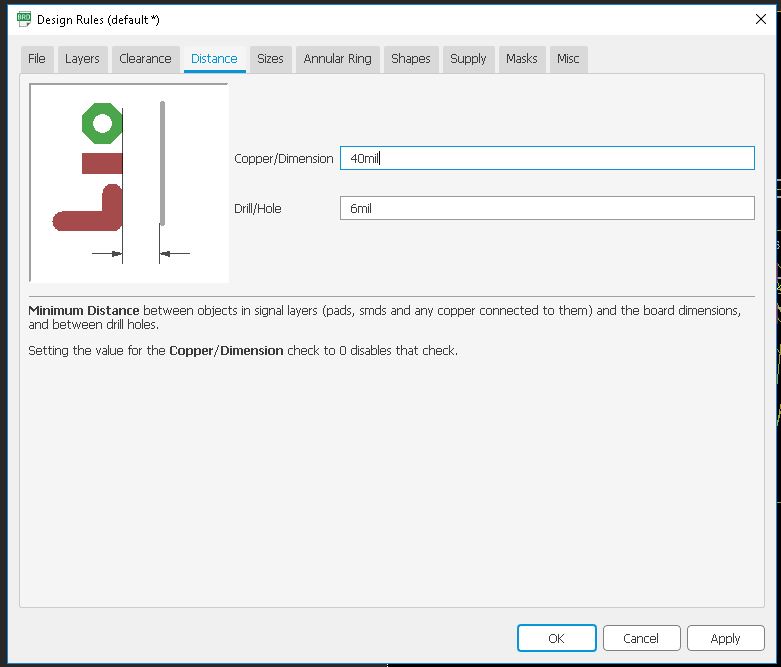
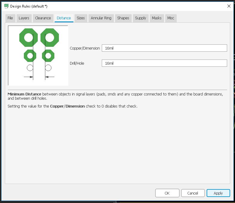
Next we need to set the Distance ,it default value is 40 mil so we need to set the value corresponding to our bit that is 16 mil.
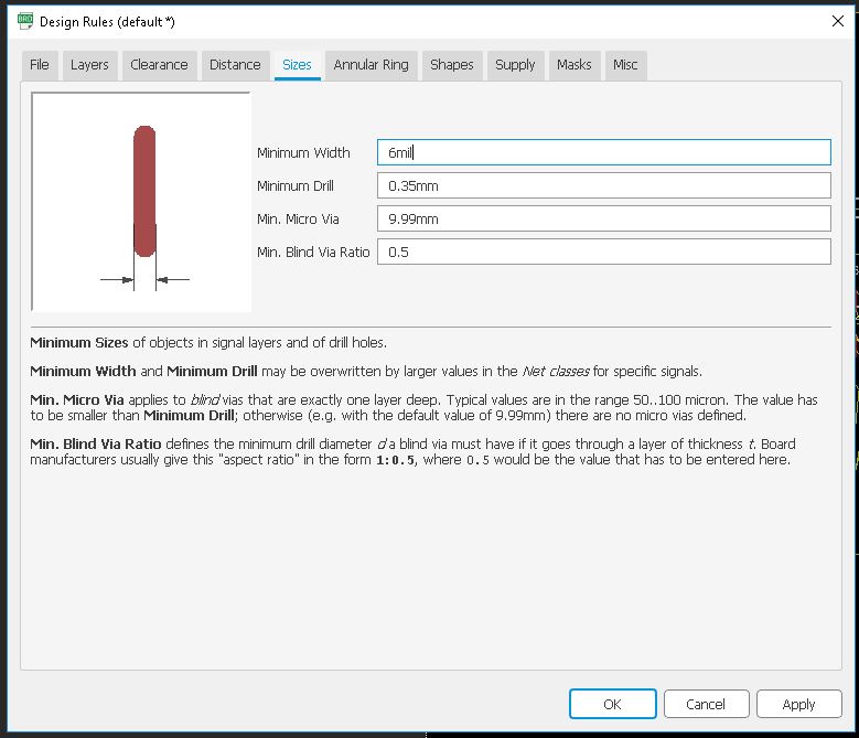
Next we need to set the Size of the Copper Trace , in defult 6mil, and we need to give 16 mil.
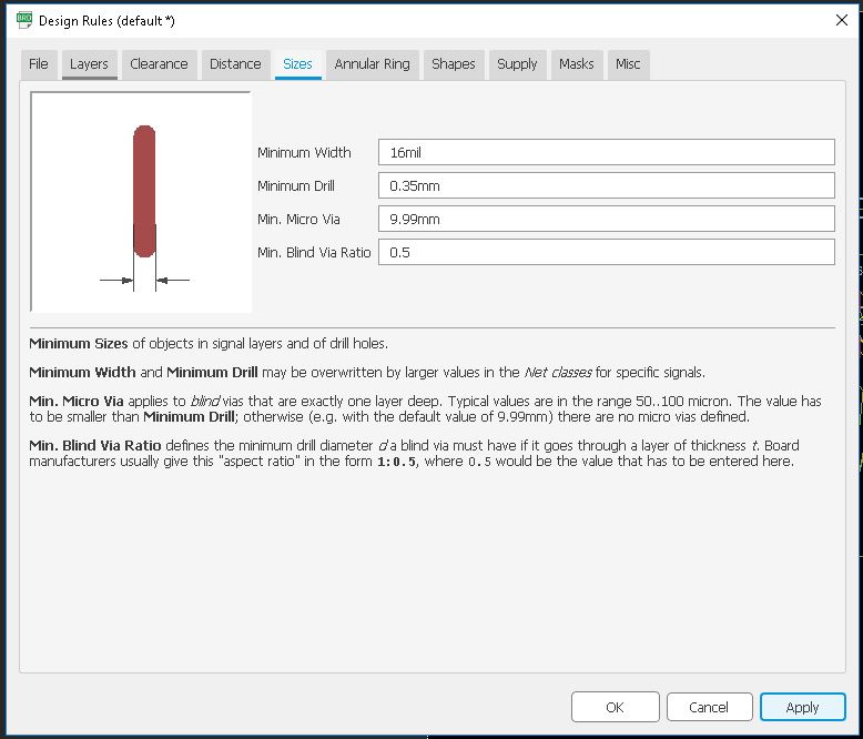
Now press OK
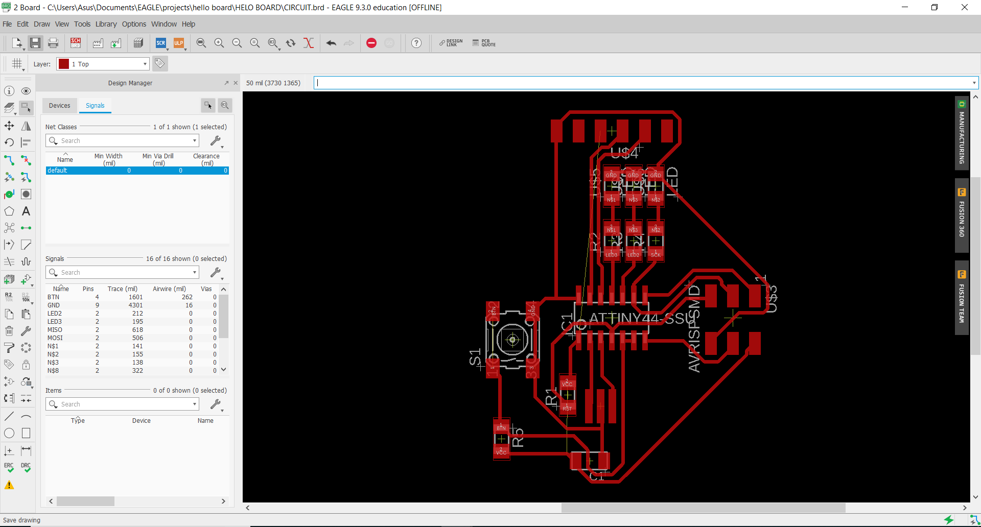
Setting up PCB
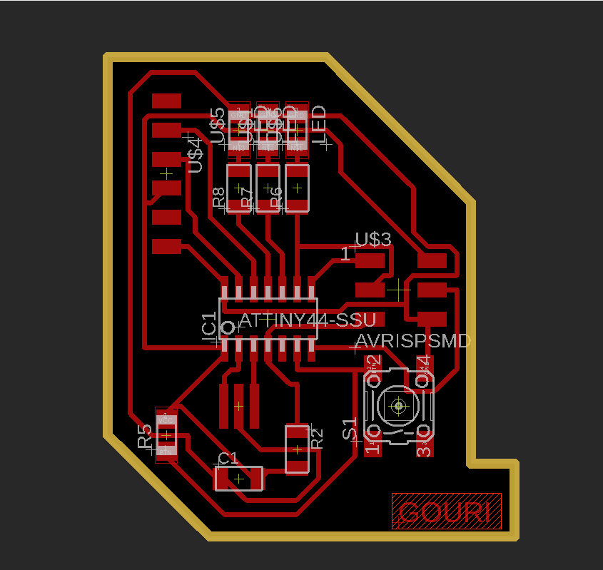
Now it is completely routed. I added an optimized border to it after that.
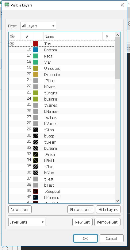
To export the mill trace and cut trace in .png format, we have to hide some layers.
Go to layers and click "Hide all layers".Also select "Top layer" to export.
tick Monochrome while exporting and set resolution to 1500.
Now repeat the same with cut line also
Now go to "File" and click "Export"
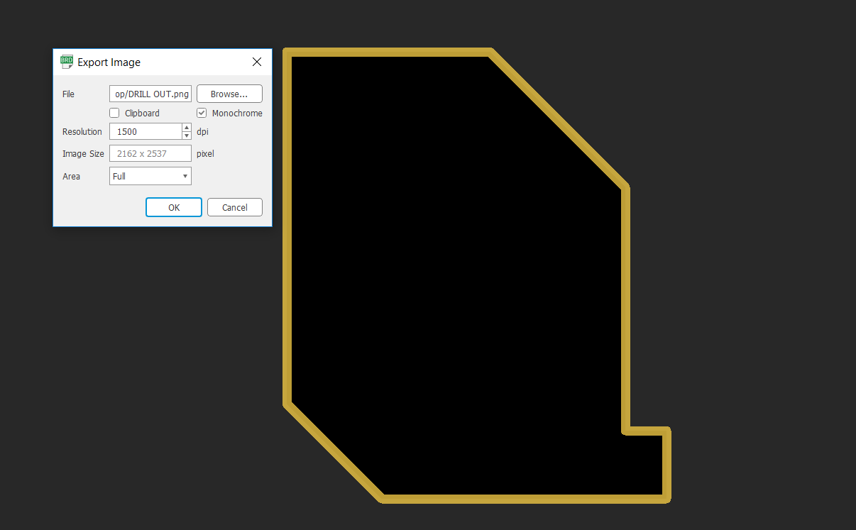
After that export the file into .png
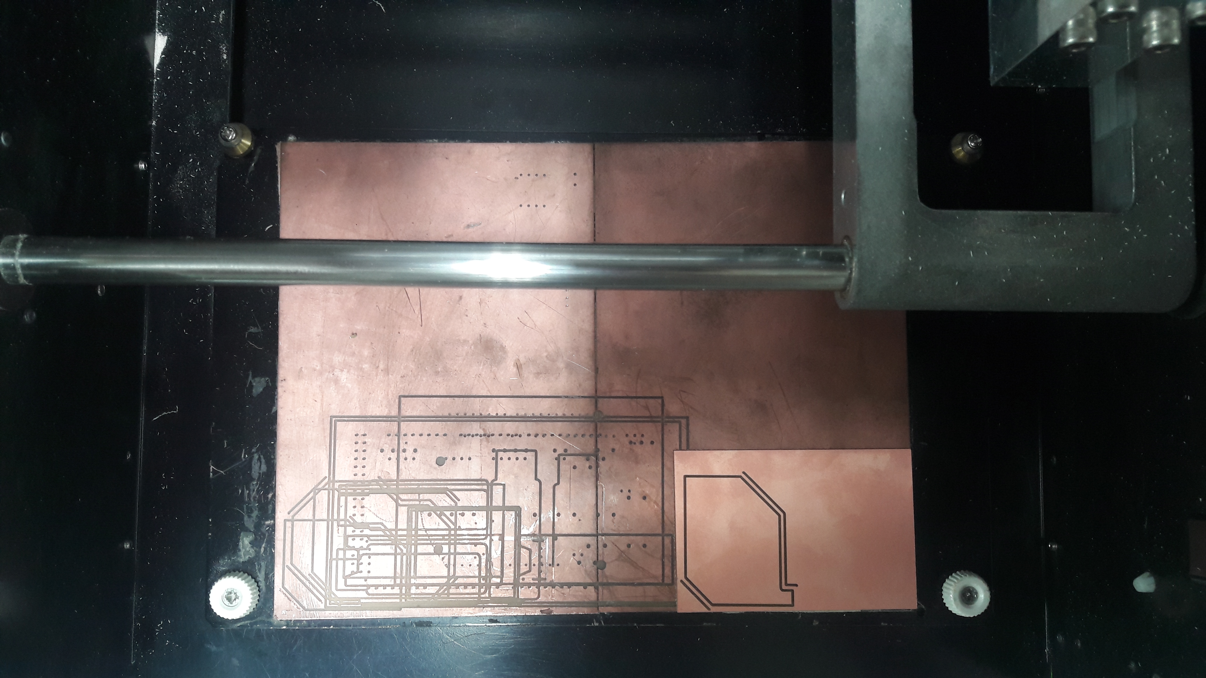
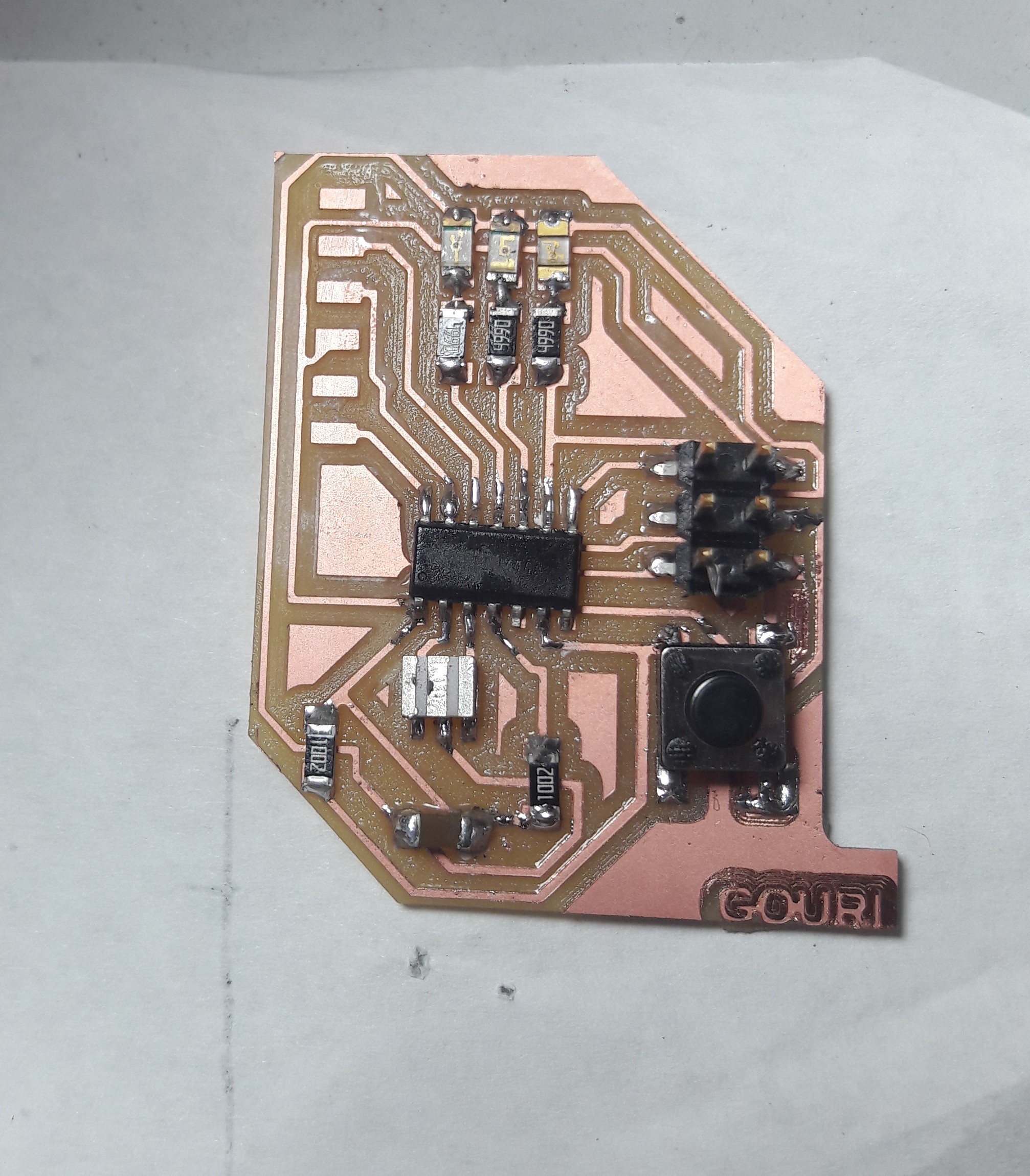
Milling and Soldering
I explaind about the PCB milling procedure in the Week5 Electronics Production. same way i am using Modela MDX for milling the PCB.
Now we need to solder it. For that first I collected the components from inventory and solder it
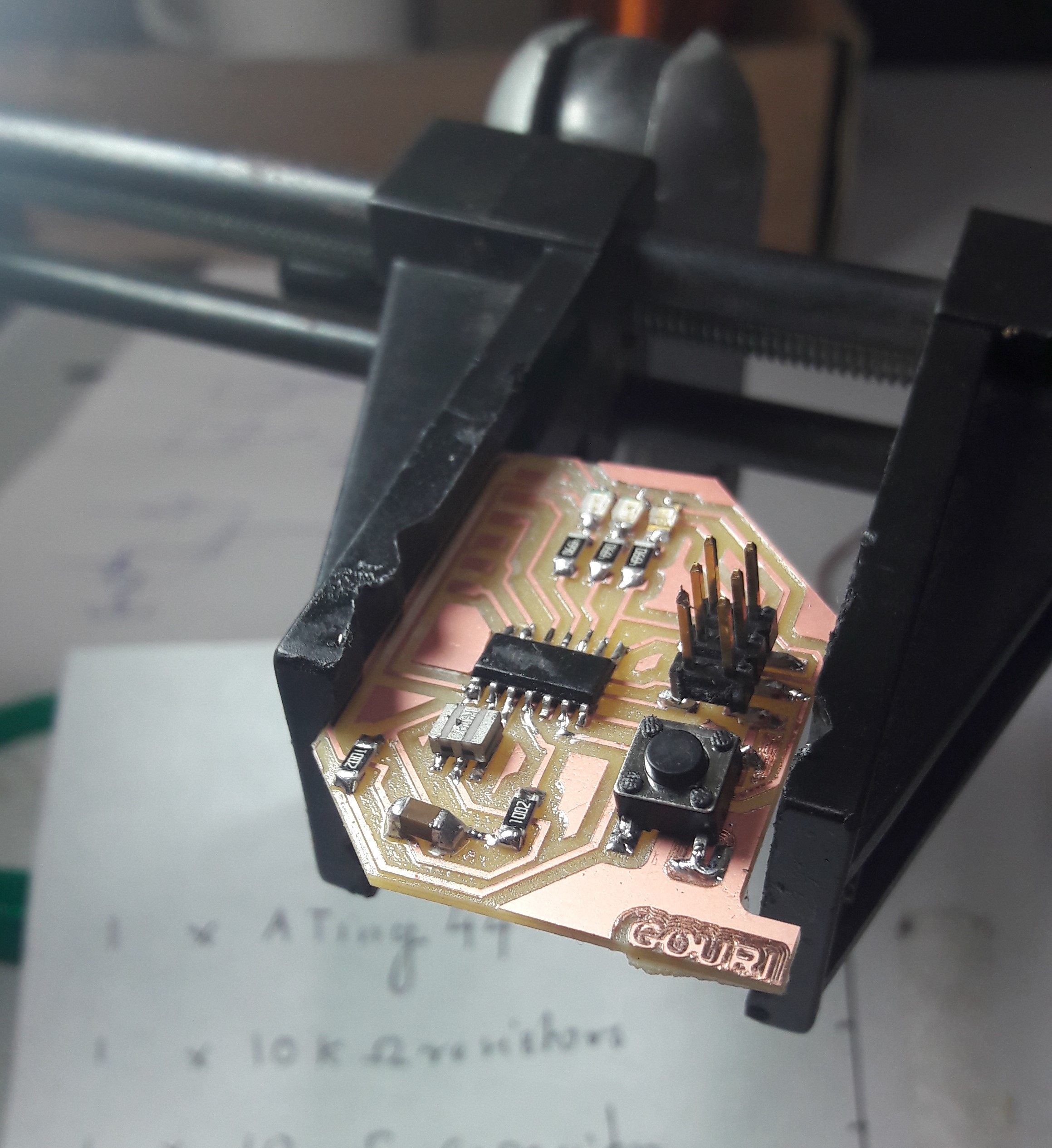
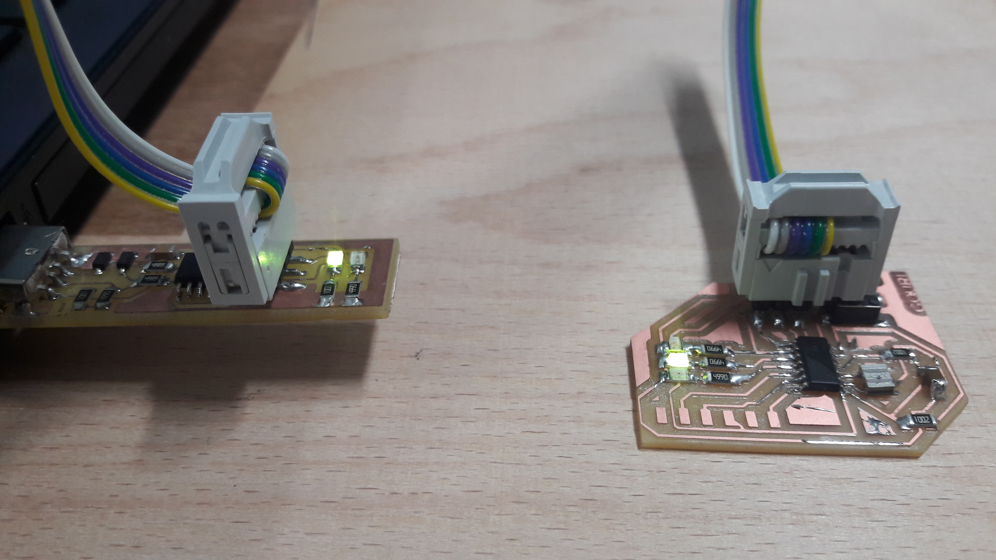
HERO SHOT
Now I need to program it. For that I opened "Arduino IDE" and entered the code
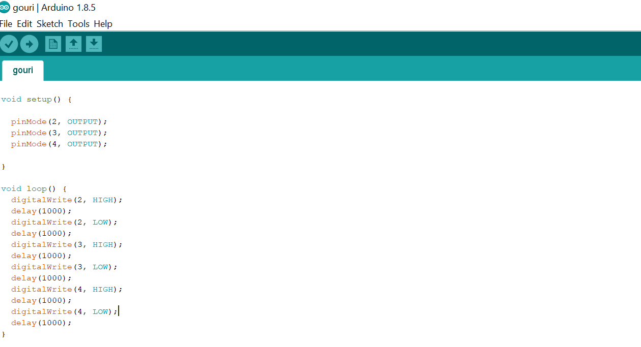
You can download the whole project from here.
Group Assignment
This week's assignment was to use the test equipment in your lab to observe the operation. So let's meet with the electronics equipment’s
Multimeter
A multimeter is a tool for testing different parameters of an electronic circuit board. In our lab, we use UNI-T UT61A multimeter. You can download the user's manual from Here
Tests can be done using Multimeter
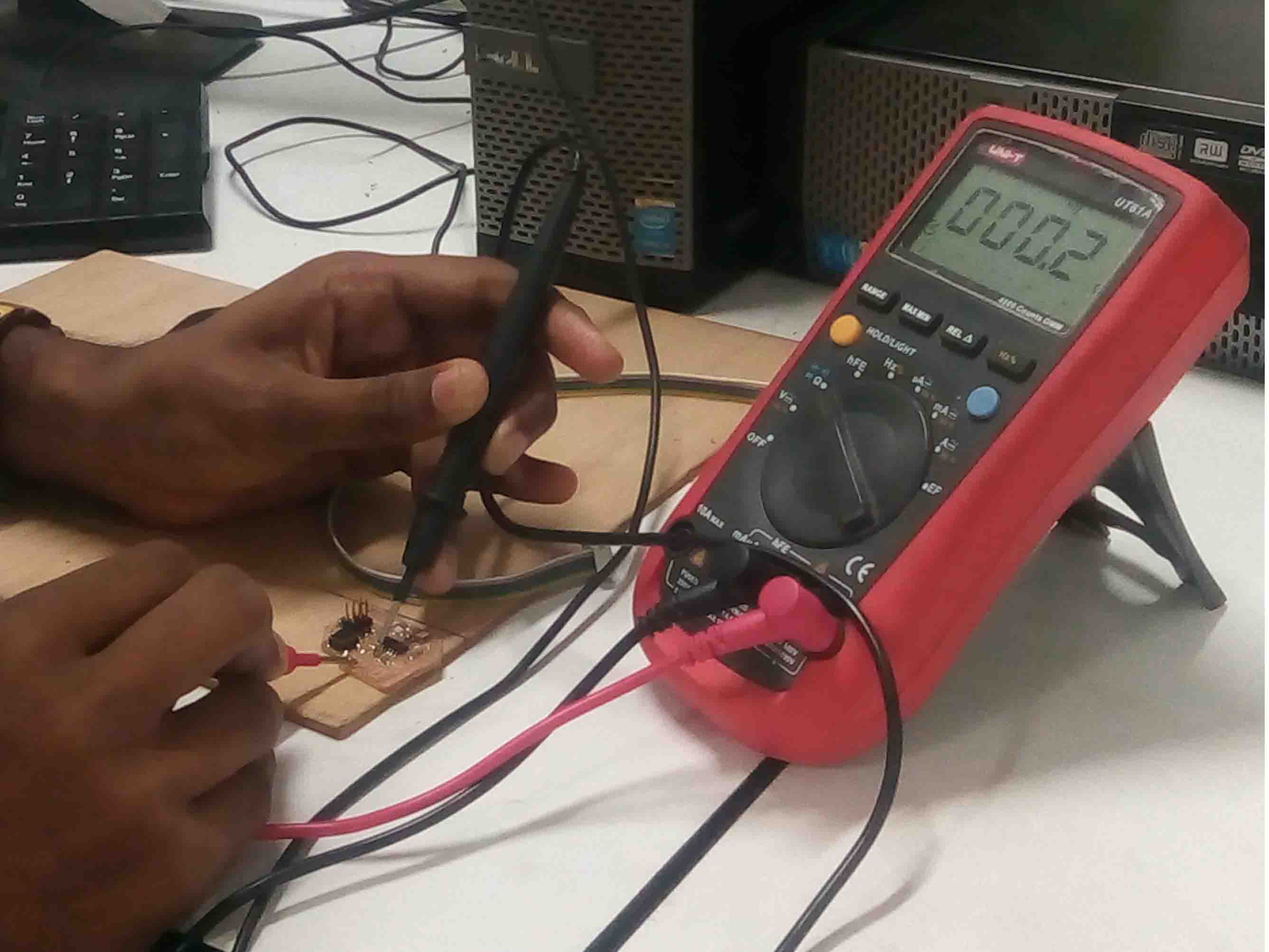
I used multimeter for testing continuity in my PCB
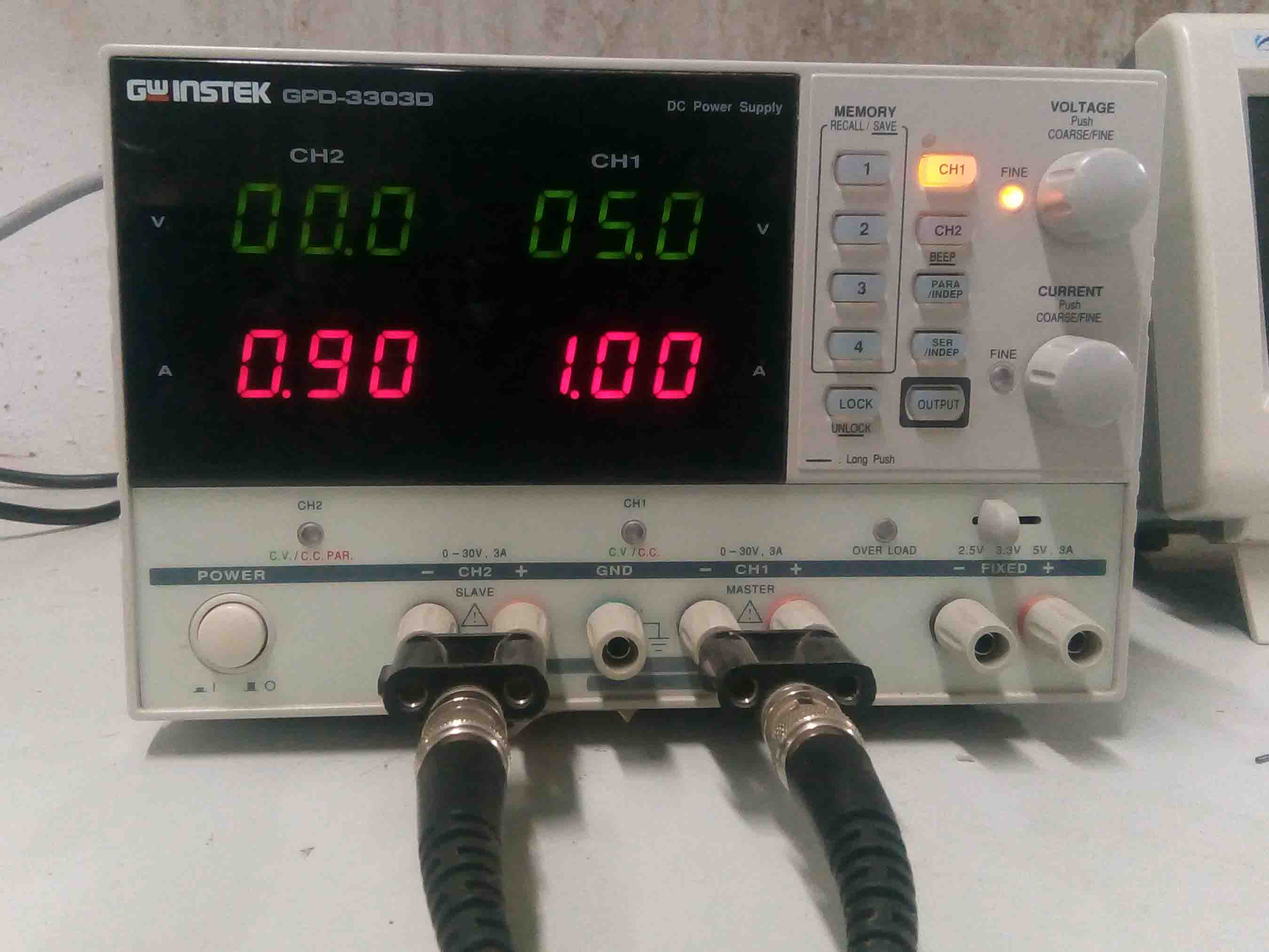
DC Power Supply

Features
- 2/3/4 Independent Isolated Output
- 4 LED Display Sets: 3 digits after decimal point
- Minimum Resolution:
- 1mV/1mA (GPD-2303D/GPD-3303S/GPD-4303S)
- 100mV/10mA (GPD-3303D)
- Digital panel control (rotary encoder Switch, rubber key with indicator)
- User-friendly operation, coarse/fine volume control
- 4 Sets Save/Recall
- Key-Lock
- Output on/off
- Tracking Series and Parallel mod
- Smart cooling fan achieving low noise
- USB Standard Interface
- PC Software & USB Driver
- Lab view driver
Digital Oscilloscope
Features
Function Generator
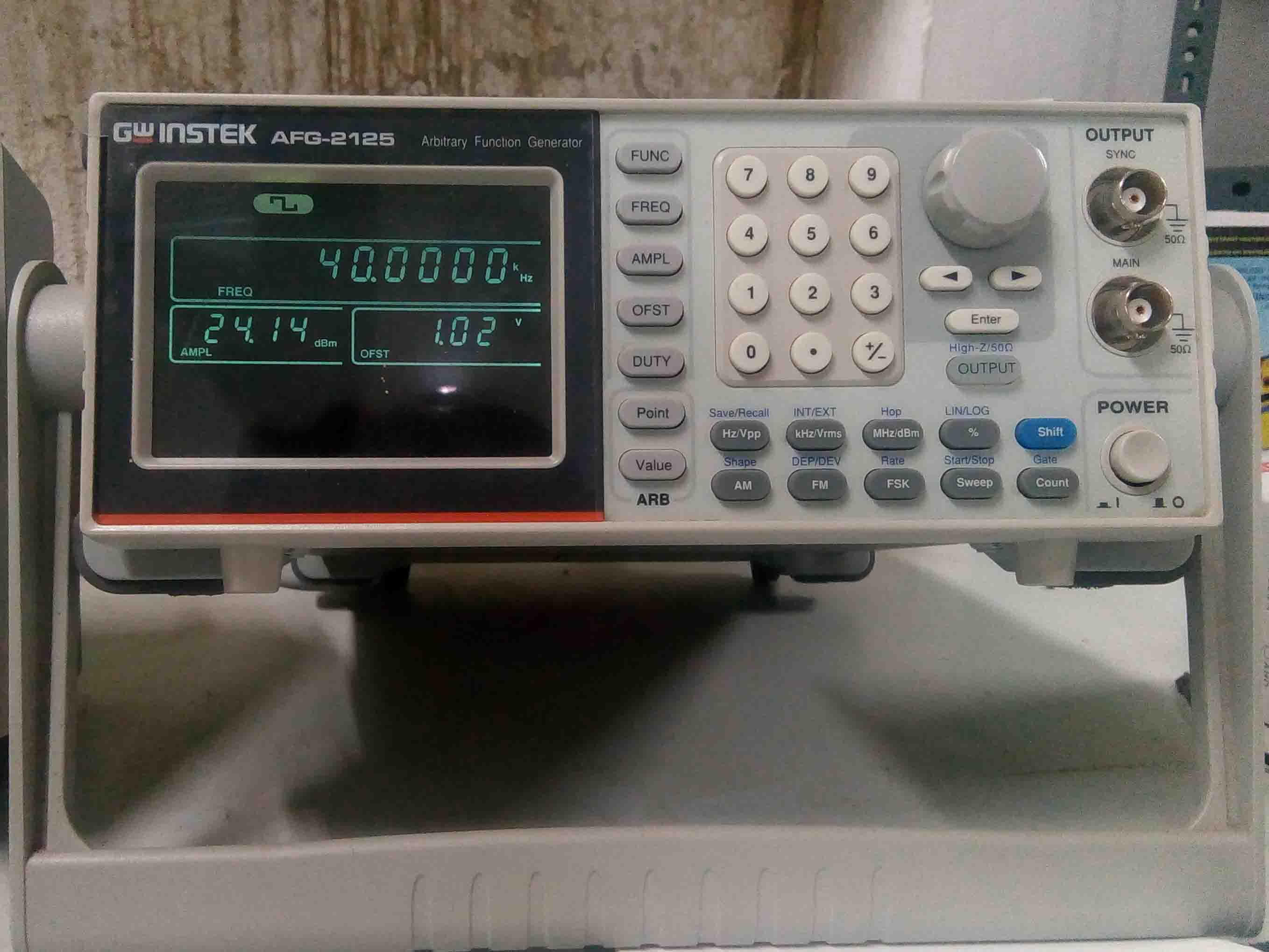
Features